Development of a Novel Robotic Testing System
FRS2010 Biomechanics Robot
The FRS2010 is a custom designed a robotic system, consisting of a 6-DOF manipulator, servomotor controllers, and a control computer. The system was designed by Hiromichi Fujie (Tokyo Metropolitan University) and assembled by Technology Services co. (Chino, Japan). The manipulator has two different moveable mechanisms. The upper mechanism consists of two translational and three rotational axes assembled in series. This unique design, optimized for joint biomechanical testing, offers very high rigidity of the manipulator and positional repeatability on the order of a thousandth of a millimeter. A universal force-moment sensor (UFS, ATI Delta IP60) is attached to the end of the upper mechanism and utilized to provide feedback control to the manipulator. The system also comes equipped with a 16 bit analog to digital board (NI USB 6225). Control of the system is accomplished through an open access Labview Program (Technology Services co.) designed for knee joint biomechanical testing and can operate in Hybrid Control, Velocity Impedance Control and Displacement Control. The system operates at a refresh rate of 5 milliseconds offering dynamic control capabilities at physiologic velocities and accelerations.


System Setup
The system was originally designed for knee joint biomechanical testing and is actively being used for ongoing investigations of the knee joint. The most recent knee study using the robot is designed to investigate the role of the anterolateral capsule in the intact knee and ACL deficient knee. The robust design of the hardware and software allows for easy customization. Therefore, efforts are underway to design and fabricate fixtures and update the Labview Software to enable biomechanical testing of any major joint of the body. Specific focus areas with the lab will include ankle, shoulder, and spine. See below for more information on these efforts:
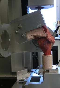
Ankle Joint Biomechanical Testing
High ankle sprains are common in contact sport such as football and soccer. A high ankle sprain typically occurs when an external rotation in applied to the ankle in prone position. The type of sprain is characterized by damage to the interosseous membrane between the tibia and fibula. Testing of a full lower leg cadaveric specimen (shank and foot) introduces additional constraints not present in knee joint testing. First, three rigid bodies (tibia, fibula, and talus) must be tracked to determine kinematics of the high ankle joint. Second, a larger specimen must be fastened to the robot for testing. In order to conduct biomechanical testing of the high ankle joint, an external motion tracking system (DMAS7) is being used to track the motion of fibula. Additionally, a customized clamp is currently being designed to suit the needs of the project.
Shoulder Joint Biomechanical Testing
The shoulder joint consists of four joints: the sternoclavicular, acromioclavicular, scapulothoracic and glenohumeral joint. They coordinate precisely and the shoulder joint can maintain a large range of motion. Among them, glenohumeral joint has greatest chance to dislocate, because of the lack of the inherent bony stability. On the other hand, the surrounding musculature, ligaments and capsule contribute to its stability. In throwing athletes, repetitive throwing motion creates a tremendous amount of force in the anterior stabilizing structures of the glenohumeral (GH) joint, including the anterior capsule. However, it is unclear which specific area of the anterior capsule becomes most stretched or permanently elongated. As a result, the thrower’s shoulder and associated injuries are not clearly understood. A robotic testing system can simulate the dynamic motion of the glenohumeral joint. The purpose of this study is to evaluate the strain in the anterior capsule of the glenohumeral joint by simulating a dynamic throwing motion using robotic testing system. This study is now in the process of validating the normal and throwing motions, using the robotic testing system.

Spine Biomechanical Testing
The human cervical spine supports substantial compressive load in-vivo arising from muscle forces and the weight of the head. However, the traditional in-vitro testing methods rarely include compressive loads, especially in investigations of multi-segment cervical spine constructs. Various methods of modeling physiologic loading have been reported in the literature including axial forces produced with inclined loading plates, eccentric axial force application, follower load, as well as attempts to individually apply/model muscle forces in-vitro. The importance of proper compressive loading to recreate the segmental motion patterns exhibited in-vivo has been highlighted in previous studies. However, appropriate methods of representing the weight of head and muscle loading are currently unknown. This study is designed to establish new cervical spine testing capabilities within a novel robotic testing system that will enable the testing to be performed at flexion rates of the same order of magnitude as the in-vivo kinematic testing is performed. We are currently in the process of determining the repeatability of the robotic testing system for spine biomechanical testing and establishing the methods to track intersegmental motion using the DMAS7 motion tracking system.